
FABRICATION OF A FIBEROPTIC SUPRASTAGE LIGHT SOURCE FOR THE BH2/BHS MICROSCOPE
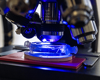
Direct lighting for microscopic observation is important for subjects which do not transilluminate substage light. This DIY fiberoptic, suprastage, direct illuminator is designed to be low cost, easy to fabricate, install and maintain. The custom fabrication permits use of any of the visible spectrum of LED light sources including white light . This becomes especially useful when the required light source must be of a specific wavelength. In this instance the subject of interest has the property of biofluoresence. Green fluorescent protein (GFP) fluoresces with the application of royal blue light ~460nm. The light source shown here is one designed for provoking dinoflagellates to exhibit bioluminesence. The substage and direct light are matched in wavelength.
PROBLEM STATEMENT:
The microscopic observation of living coral for multiple days requires specific environmental controls that include temperature, light, nutrients, pH control, nitrate and phosphate regulation, and steady salt water flow rate. Additionally videography and stop motion time laps photography require complete lack of vibration and stable ambient temperature. This direct illumination is highly controlled. All heat sources are substantially distant from the microscope and there is no vibration. The direct light source is not attached to the microscope and any movement of the light or the stage does not affect one another.
This illuminator was developed in tandem with a LED for substage illumination. The Knapp BH2/BHS illuminator is described in a previous web posting . The paired illuminators are used for in-vivo bioluminescent studies. A future postings will describe the blocking filtration modification of the microscope.
List of materials;
- Fiberoptic cable
- Goose neck support
- Barbed end plastic tubing connectors
- Zip ties
- Heat sink
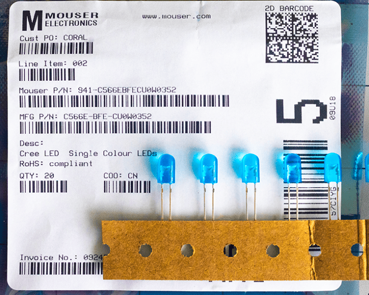
- Royal blue (~460nm) LED bulb
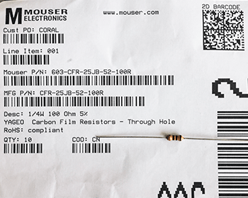
- Inline resistor
- Rosin core solder
- Weighted end support
- Power supply
Tools:
- Soldering iron
- Drill bit
- Electric drill motor
POWER SOURCE:
Variable Power supply is available for purchase from the Empire of Dirt Workshop (empireofdirtworkshop.com) or contact Carl (carlh6902@gmail.com)
Disclaimer: I did not collaborate with Carl regarding the use of his power source. He makes his own design exclusively for Olympus BH2 microscopes. This illuminator is my design for BH2/BHS Olympus microscopes. I did fabricate a dual outlet extension cord which can be plugged into the LED outlet on the power supply. This allows for simultaneous dual illumination from one power source. The duplex container was fabricated from available PVD parts.




Discussion:
The bulb/resistor assembly could have been compartmentalized to allow quick interchanging with alternative resources however at this time this combined unit is sufficient for the requirements of this project. Resistor may be exchanged to provide different brightness. The LED may be exchanged for different wavelength. I have not tried alternative wavelengths. Ultraviolet wavelengths might be interesting. The one meter length of fiberoptic cable probably could be shortened by 1/2 to reduce light transmission loss. I expect that this device would provide excellent direct illumination for nearly any standard microscope.
Resistor and Power Calculations:
A 5mm oval 460nm (blue) Cree C566E LED typically operates at a forward voltage (V_{f}\) of approximately 3.2V. To run it safely at a standard target current of 20mA (0.02A) from the 6V supply, use the following specifications:
Calculated resistance: (140 Ohm) Uses a standard 150 Ohm resistor.
Resistor Power Dissipation: The resistor will drop 2.8V at 0.02A, dissipating 0.056W. A standard 0.25W (1/4 watt) resistor is sufficient. (Note: While the power supply can deliver up to 2A, the resistor ensures the LED only draws the 20mA it requires). If the 20mA is not bright enough for fast shutter speed photography through the SPLAN 40 (which has a narrower aperture and requires more light), the Cree C566E lamp can tolerate power up to 30mA. To attain the 30mA Formula: Swap the resistor for a (100 Ohm) component. This increases brightness by 50% but will make the LED run slightly warmer. The included LED enclosure design is a small aluminum heatsink.
DIY cost not including power supply ~$30.00
#microscope #illuminator #light source #direct lighting #blue light #fiberoptic #bioluminescence
If you wish to be notified of future postings please enter you email and click on subscribe
Please feel free to comment. Don’t forget to like this post!
Please help to improve the site. Leave a comment