DIY Fiberoptic Illumination for Olympus BH2/BHS Microscope

FABRICATION OF A FIBEROPTIC SUPRASTAGE LIGHT SOURCE FOR THE BH2/BHS MICROSCOPE

Direct lighting for microscopic observation is important for subjects which do not transilluminate substage light. This DIY fiberoptic, suprastage, direct illuminator is designed to be low cost, easy to fabricate, install and maintain. The custom fabrication permits use of any of the visible spectrum of LED light sources including white light . This becomes especially useful when the required light source must be of a specific wavelength. In this instance the subject of interest has the property of biofluoresence. Green fluorescent protein (GFP) fluoresces with the application of royal blue light ~460nm. The light source shown here is one designed for provoking dinoflagellates to exhibit bioluminesence. The substage and direct light are matched in wavelength.

PROBLEM STATEMENT:

The microscopic observation of living coral for multiple days requires specific environmental controls that include temperature, light, nutrients, pH control, nitrate and phosphate regulation, and steady salt water flow rate. Additionally videography and stop motion time laps photography require complete lack of vibration and stable ambient temperature. This direct illumination is highly controlled. All heat sources are substantially distant from the microscope and there is no vibration. The direct light source is not attached to the microscope and any movement of the light or the stage does not affect one another.

This illuminator was developed in tandem with a LED for substage illumination. The Knapp BH2/BHS illuminator is described in a previous web posting . The paired illuminators are used for in-vivo bioluminescent studies. A future postings will describe the blocking filtration modification of the microscope.

List of materials;

  • Fiberoptic cable
  • Goose neck support
  • Barbed end plastic tubing connectors
  • Zip ties
  • Heat sink
  • Royal blue (~460nm) LED bulb
  • Inline resistor
  • Rosin core solder
  • Weighted end support
  • Power supply

Tools:

  • Soldering iron
  • Drill bit
  • Electric drill motor

POWER SOURCE:

Variable Power supply is available for purchase from the Empire of Dirt Workshop (empireofdirtworkshop.com) or contact Carl (carlh6902@gmail.com)

Disclaimer: I did not collaborate with Carl regarding the use of his power source. He makes his own design exclusively for Olympus BH2 microscopes. This illuminator is my design for BH2/BHS Olympus microscopes. I did fabricate a dual outlet extension cord which can be plugged into the LED outlet on the power supply. This allows for simultaneous dual illumination from one power source. The duplex container was fabricated from available PVD parts.

A black electronic device with a heatsink, connected to a cylindrical white component with wires on a grid background.
Power supply with Knapp duplex
A close-up image of a coiled black wire with two blue LED lights at either end, placed on a grid-patterned surface.
Fiberoptic cable, end glow, 5mm diameter, 1M length
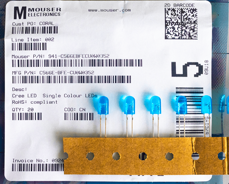
A label from Mouser Electronics showcasing a product order, featuring details like item number, description of Cree single color LEDs, and a quantity of 20, alongside several blue LEDs attached to a brown card.
LED bulbs royal blue ~460nm.
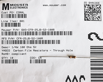
Receipt for a purchase from Mouser Electronics, featuring carbon film resistors, including details such as part numbers and quantity.
One of two options for resistor choices needed to protect the LED.
A blue LED and a resistor connected by wires on a grid background.
Solder the resistor to the positive end of the LED and to the (+) side of the power supply.
A black flexible hose with a red lever and a clamp attachment, laid out on a grid background.
Stiff goose neck support modified by zip ties holding a series of plastic hose couplings. The cable was passed through the couplings
Close-up of a fiberoptic cable with a black rubber sheath, showing an end glow, and an LED with a resistor assembly double wrapped in heat shrink.
The LED is in direct contact with the fiberoptic cable
Close-up of a metallic component with grooves and a circular opening, set against a grid background.
Heat sink with central hole enlarged by drilling to fit the cables.
Close-up of a cable showing a heat sink and labeled connection points for optical and electrical connections.
Fiberoptic cable press fit end to end with the LED power cable held together by the heat sink.
Close-up of a black cable with electrical connectors, lying on a grid-patterned surface.
Completed optical and electronic transmission cable assembly.
Close-up of black tubing secured with zip ties to provide support for a fiberoptic cable.
The tubing allows the cable end to be advanced or retracted from the specimen.
A photo of a gooseneck light fixture, featuring a weighted stand, a power plug, and a light connection, with labels indicating each component.
Completed assembly of the Knapp fiberoptic illuminator. The weight stand is not specific but must be suitable to provide stability.
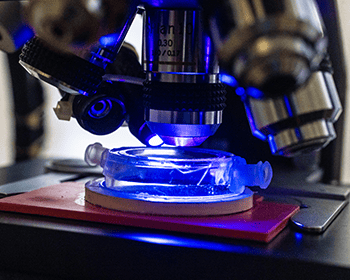
Close-up view of a microscope focusing on a glass slide illuminated by blue light.
Custom, closed cell, micro aquarium illuminated by the ~460nm light directed on the surface by the glow end of the fiberoptic cable.

Discussion:

The bulb/resistor assembly could have been compartmentalized to allow quick interchanging with alternative resources however at this time this combined unit is sufficient for the requirements of this project. Resistor may be exchanged to provide different brightness. The LED may be exchanged for different wavelength. I have not tried alternative wavelengths. Ultraviolet wavelengths might be interesting. The one meter length of fiberoptic cable probably could be shortened by 1/2 to reduce light transmission loss. I expect that this device would provide excellent direct illumination for nearly any standard microscope.

Resistor and Power Calculations:

A 5mm oval 460nm (blue) Cree C566E LED typically operates at a forward voltage (V_{f}\) of approximately 3.2V. To run it safely at a standard target current of 20mA (0.02A) from the 6V supply, use the following specifications:

Calculated resistance: (140 Ohm) Uses a standard 150 Ohm resistor.

Resistor Power Dissipation: The resistor will drop 2.8V at 0.02A, dissipating 0.056W. A standard 0.25W (1/4 watt) resistor is sufficient. (Note: While the power supply can deliver up to 2A, the resistor ensures the LED only draws the 20mA it requires). If the 20mA is not bright enough for fast shutter speed photography through the SPLAN 40 (which has a narrower aperture and requires more light), the Cree C566E lamp can tolerate power up to 30mA. To attain the 30mA Formula: Swap the resistor for a (100 Ohm) component. This increases brightness by 50% but will make the LED run slightly warmer. The included LED enclosure design is a small aluminum heatsink.

DIY cost not including power supply ~$30.00

#microscope #illuminator #light source #direct lighting #blue light #fiberoptic #bioluminescence

If you wish to be notified of future postings please enter you email and click on subscribe

Please feel free to comment. Don’t forget to like this post!

Olympus BH2/BHS Illuminator DIY Upgrade

FABRICATION OF A REPLACEMENT SUBSTAGE LIGHT SOURCE FOR THE BH2/BHS MICROSCOPE

A square electronic component with a black cylindrical outlet and a ribbed ventilation grill on top.

Figure 1.  Olympus OEM illuminator housing, bulb, magnifier, diffuser, mounting tube and electrical connector. Not included in image are the transformer, electrical components and controller which are in the base of the microscope

The purpose of this posting is to satisfy the needs of amateur microscopists using Olympus model BH2/BHS with a failing illuminator. It is designed to be low cost, easy to fabricate, install.and maintain.

The BH2/BHS microscope has a substage incandescent light source that is standard with the instrument. The light source required a 120 V power source which is modified by a transformer and microcircuitry built into the base. There are two controllers for this lamp including a on/off power switch and a sliding potentiometer for intensity control. 

PROBLEM STATEMENT:

The sliding potentiometer is no longer in production  and all online inventory resources for a single replacement this part are out of stock. My Olympus BH2/BHS potentiometer was out of function. Attempts to clean it without disassembly of this substructure were unsuccessful. The other option was to replace the entire light source system with a new low voltage LED bulb.

The housing for the new light source was fabricated from easily available PVC plastic plumbing materials. Other materials listed below were easily purchased from online suppliers. 

LIST OF PARTS OF THE ASSEMBLY:

1 !/2 X 2-inch PVC coupling

2″ PVC Pipe Vent Screen, 2.375″ OD, 1/2″ mesh

5/8-inch length of 1-inch PVC plastic pipe

Low voltage DC power cable, 5.5mm X 2.1 male connector ~ 10 inches of  ~20 ga twin wire

Round Heat sink,  1 inch outside diameter, 2-inch length with internal space for placing screws

2 machine screws to fit the apertures in the heat sink (your choice)

2-inch disc of sheet ~1mm aluminum, (Secured from scrap packaging)

Aluminum tube 47mm OD X 78mm length 

LED star with light frequency of your choice. (I used 460mm for the royal blue).

Thermo-adhesive for attaching LED star to the heatsink 

Metallic duct tape to apply to the ID of the microscope substage rear illuminator port

Plastic 0.5mm clear plastic shim stock, (1cm X 15cm strips cut from scrap packaging)

TOOLS NEEDED:

Saw, to cut PVC and aluminum tubing (hand saw or power miter saw)

Scissors, to cut sheet aluminum and plastic

Soldering tool, for micro circuitry with rosin core solder

Thread tap, with sized drill bit for attaching the heat sink to the sheet aluminum mounting plate

Power drill motor

POWER SOURCE:

Variable Power supply available and purchased from the Empire of Dirt Workshop (empireofdirtworkshop.com) or contact Carl (carlh6902@gmail.com)

Disclaimer: I did not collaborate with Carl regarding the use of his power source. He makes his own design exclusively for Olympus BH2 microscopes. This illuminator is my design for BH2/BHS Olympus microscopes.

RESULT:

The new Olympus BH2/BHS microscope illuminator together with the power source provides perfect lighting for Olympus SPlan 5X, 20X, and 40X lenses. The heat generated from the illuminator assembly is minimal. Heat generated from the power source is also well dispersed from the heat sink of the power source. 

I constructed three light sources using this method; white light, royal blue and royal blue with a fiberoptic cable for direct illumination. The royal blue light provides illumination to reacts with the green fluorescent protein in the marine organism subjects. 

The internal electronics in the base of the microscope are not used but remain to maintain the mass of the instrument thus reducing photographic image blur from extraneous vibrations.

COST:

Not including the transformer and power source, the total cost of parts and materials was less than $50. Including the initial cost of the first unit the cost of three illuminators was less than $75 and I still have excess remaining materials.  

Note Not shown here is the fiberoptic illuminator. That deserves its’ own presentation.

ILLUSTRATIONS:

A close-up view of a white plastic pipe fitting on a grid pattern background.
Figure 2  PVC coupling
A white circular plastic ring placed on a grid-patterned surface.
Figure 3  section of PVC 1-inch pipe
White PVC pipe fitting viewed from above, showing a circular design with an inner diameter.
Figure 4  Check of fit of PVC pipe inside of coupling
Three white plastic pipe fittings on a gray grid background, including a round connector, a smaller ring, and a circular grating cover.
Figure 5 PVC parts to make illuminator housing
A broken white ring placed on a grid-patterned surface.
Figure 6  Section of PVC with V shaped split to trap wire
Close-up of a white circular plastic pipe fitting on a grid mat.
Figure 7  PVC coupling with notch to accommodate wire
A white PVC pipe fitting, a round metallic disc, and an aluminum heatsink on a grid-patterned surface.
Figure 8  PVC Coupling with sheet aluminum and heat sink
Top view of a white plastic container with a metal base featuring two holes.
Figure 8  Sheet aluminum with holes drilled to receive retaining screws
An electrical wire with a 5.5mm x 2.1mm male connector, an LED circuit board, and a heat sink on a grid surface.
Figure 10  Electrical components ready to assemble.

Close-up view of a LuxorDrive component with textual details and electrical contacts on the top surface.
Figure 11 LED star glued to heat sink.
A white PVC pipe fitting next to a circular aluminum LED heat sink with electrical wiring attached.
Figure 12  Heat sink with wired soldered to LED star, adhered to the heat sink and screwed to the plate ready for assembly into PVC housing.
Top view of a white LED light housing with wires and a circuit board inside.
Figure 13  Heat sink with wire and LED and mounting plate inserted into housing. Some notching was needed to pass the wire through the plate and the side of the interior of the housing
Close-up view of a white cylindrical device with electrical wires, placed on a grid-patterned surface.
Figure 14 Side view of heat sink with wire and LED and mounting plate inserted into housing.
Close-up view of a white plastic electrical junction box with two screws inside and a black wire attached, next to a removable cover with a grid pattern.
Figure 15  View of the interior of the larger end of the PVC housing. Note the path of the wire through the notched plate and housing side and retained in the V of the split ring of PVC. Notch in end cap.
A cylindrical metal tube with a smooth surface, placed on a grid-patterned surface.
Figure 16  The aluminum tube to be used for mounting to the microscope
Disassembled components of a lighting fixture including a white socket, a gray cylindrical body, a mounting ring, and a white grid cover.
Figure 17  Full display of parts in the illuminator ready for final assembly.
A disassembled device featuring a cylindrical metal base with a white plastic top, a black wire protruding from it, and two separate white plastic components including a ring and a cover with a grid pattern.
Figure 18  Rear stack of PVC parts 
A white and silver cylindrical container with a removable top and a grid-patterned cover next to it. A black wire is visible inside the container.
 Figure 19  Wire captured in split ring ready to close with the vented cover.
A close-up of a cylindrical device with a white top featuring a grid pattern, attached to a metallic cylinder below, and a black wire extending from the side.
Figure 20  Fully assembled illuminator. Use sheet plastic shim stock to fill the spaces and make a sturdy assembly.
Close-up of a cylindrical opening on a machine with a textured surface and control dials.
Figure 21  Interior of the rear illuminator light port modified with parches of 4 layers of aluminum duct tape to make a snug fit for the new illuminator
Close-up of a ventilation grille on the back of a device, featuring a circular design with a grid pattern and a cable attached.
Figure 22  LED illuminator in place ready for first light.
A collection of four electrical components arranged in a row on a grid background, labeled as Transformer, Power Supply, White Light, and Royal Blue Light.
Figure 23  Completed illuminator replacement kit including transformer, variable power supply, and both the white light source and blue light source.
Image showing a power supply unit on the left, and two light fixtures labeled 'ROYAL BLUE' and 'WHITE' on the right, casting different colored lights.
Figure 24 Power source illuminating both white and blue LEDs
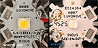
Top view comparison of two LED light components, one labeled 'White LED' and the other 'Blue LED,' showcasing their different color chips and design features.
LED lights: White LED Star Cree XLamp B009-CL2075OU3; Blue LED Star Cree XLamp XT-E Royal-Blue A007 E514064

I made two illuminators for specific purposes. The white is for general transillumination. The royal blue is for study of coral polyps with green fluorescent protein bioluminescence. I hope that this keeps all of the Olympus BH2/BHS microscopes working for more years to come.

Just wait until you see the fiberoptic direct illuminator.

#microscope #illuminator #light source #indirect lighting #blue light #fiberoptic #bioluminescence

If you wish to receive notification of postings please enter your email and click on subscribe.

Please enter your comments in the space provided.

Powered by WordPress.com.

Up ↑