Micro Aquarium Closed Cell System for In-Vivo Coral Research

Introduction:

This presentation details the materials and method for observation of coral reef polyps at a microscopic level in a controlled laboratory setting. It was designed and fabricated to significantly reduce operational complexity, maintenance, and overall cost. Research on coral reefs is traditionally conducted in large, multi-gallon, open-tank aquariums housed in designated isolation rooms to strictly control atmospheric conditions. Those systems are supplied with hundreds of gallons of carefully formulated and monitored artificial seawater, allowing for macro- and microscopic in-vivo and in-vitro observations.

For researchers interested in in-vivo marine life microscopy, this document describes a highly integrated component and support system. The microscope lighting and viewing modifications can be found on these previous posts. Substage lighting, fiberoptic direct lighting, blocking filter.

Distributed Support Network:

This is part of research of reef coral polyps. It utilizes a distributed support model that relies heavily on a collaborative partnership with a well-established local commercial aquarium facility1. Aquariums Inc is located within five miles of the research laboratory. Mr. Ryan Bollinger with 20 years of experience and his cooperative staff are highly capable. The facility acted as the specimen procurement agent and managed the long-term housing and husbandry of the primary brain coral sample within their controlled systems.(Indo-Pacific “Maze Brain” Coral (Platygyra species) or “Favites” Brain Coral)

Additionally, the partner provided essential supplies, including specialized artificial seawater and reagents for experimental materials, alongside consultation on coral physiology and behavior. The facility continuously monitors and logs environmental data for their large-scale systems. Notably, while housed at this facility, the experimental subject coral was separated from, but cohabitated with, a diverse variety of other coral species.

System Architecture and Spatial Zoning:

An upright Olympus BH2/BHS microscope was utilized to study coral polyp physiology. The standard orientation for the specimen within this system is negative geotropic (upright). This also facilitates natural water flow consistent with open-ocean environments.

To ensure the system fits comfortably on the Olympus BH2/BHS stage and clears the 20x objective lens, the apparatus was split into two functional zones:

  1. The Micro-Chamber: Located directly on the microscope stage.
  2. The Life Support Package: Positioned adjacent to, but separate from, the microscope workspace.

1. The Micro-Chamber (Stage Component):

  • Base Material: A Nunc 27 mm glass-bottom petri dish. Approximate volume ~ 5cc.
  • Viewing Window: The chamber floor consists of #1.5 cover glass (0.17 mm thickness). Because the Olympus BH2/BHS optics are precisely corrected for this specific thickness, using standard thick plastic petri dishes would introduce severe spherical aberration and degrade image sharpness.
  • Chamber Height: 2.0 mm to 3.5 mm. This dimension provides sufficient vertical clearance for the polyps to extend their tentacles without contacting the upper ceiling, while remaining thin enough to minimize total fluid volume and stay within the optical working distance.
  • Fluid Ports: Barbed miniature Luer fittings (1/16″ ID) are pressed and sealed directly into opposite sides of the chamber walls to serve as inflow and outflow ports.
  • Port Modification Process: Two or more 3/32-inch holes were drilled into the side of the glass side of the petri dish. Before insertion, a 1.5-mm length of 1/16-inch silicone tubing was fitted over the barbed end of a male Luer lock fitting. This assembly was then pressed through the 3/32-inch hole. Once seated inside the chamber wall, a second 1.5- mm length of silicone tubing was secured onto the interior section of the barbed fitting. This sandwiched configuration creates a completely watertight seal while allowing a slight range of motion. This will be described in detail later*

2. The Life Support Package (Off-Stage Component):

The life support package* consists of the artificial seawater reservoir, a peristaltic pump and connecting silicone tubing. To eliminate mechanical vibration, the pumping apparatus was isolated on a surface completely decoupled from the microscope workbench. Light and ambient temperature are centrally controlled and not further discussed in detail here.

The laboratory environment was temperature-controlled to 74°F ± 1°F. Indirect lighting was strictly regulated for both duration and intensity to preserve natural behaviors during protracted time-lapse photography sessions.

3. Flow Cell Stage Support Assembly}

To ease manipulation of the Micro-Chamber on the Olympus microscope stage, a custom support assembly was designed and fabricated. The design criteria required a low profile to fit the narrow clearance between the lens and the stage, a watertight seal while inverted, and straightforward fabrication. This assembly allows the specimen to be precisely positioned using the microscope’s standard slide holder.

Red rectangular panel with a large circular cutout against a gridded background
Fig 1 Base plate made from plastic 2mm sheet stock cut to fit microscope stage slide holder. View hole is slightly smaller than Nunc dish
Orthodontic bracket kit labeled Standard Roth 0.022-inch with brackets arranged by tooth position.
Fig 2 Dental orthodontic brackets were sourced from online web site
White circular ring on a gray grid background
Fig 3 PVC ring cut from 2″ stock
Top view of a red rectangular craft project with a large white circular ring and metal clips on a gridded cutting mat
Fig 4 Brackets and PVC ring glued to flat plastic stock
Close-up of a pink circular craft device with a white ring and metal fasteners on a cutting mat.
Fig 5 Assembled plate with plastic half of Nunc petri dish
Three transparent circular rings arranged on a gridded surface
Fig 6 Nunc petri dish open with silicone gasket for insertion
Top view of a red rectangular mounting plate with a white circular opening and four metal fasteners on a gridded background.
Fig 7 Plastic half of petri dish with gasket inserted
Close-up of a silver metal ring with several cream-colored rings attached, hanging on a white grid wall
Fig 8 Stainless steel split ring with six elastics attached ready for underwater assembly
Top-down view of a circular white device mounted on a red rectangular base with wires and clamps.
Fig 9 Aquarium partially filled with water closed with compression mechanism
Top-down view of a circular metal component mounted on a red base with multiple wire connections
Fig 10 Aquarium in stage support on microscope stage with slide retainer
Laboratory microscope examining a prepared slide under illuminated objective lenses
Fig 11 Aquarium on stage under Olympus LWD CD Plan 20 X objective lens
Exploded view of a microscope stage flow cell support with silicone seal, retaining ring, dish bottom, dish top with glass, and elastic bands
Fig 12 Exploded view of compression parts
  • Base Plate: Fabricated from flat PVC sheet stock cut to fit the microscope stage, featuring a central aperture slightly smaller than the diameter of the Nunc petri dish. Fig 1
  • Stabilizing Ring: A short cylinder of 2 inch PVC pipe, with a 39mm internal diameter matching the outer diameter of the dish, was bonded concentrically over the base aperture to align and predictably stabilize the chamber. Fig 3,4,5.
  • Compression Mechanism: Orthodontic brackets were bonded to the surrounding PVC base using cyanoacrylate adhesive. Fig 2, 5. A silicone gasket was placed on the resin floor of the dish. Fig 8. A custom metal split-ring was fitted against the outer cover glass surface of the dish Fig 9. Elastic bands were hooked onto the metal ring and stretched to engage the orthodontic brackets. Fig 10 Spacing six elastic bands equally distributed the downward pressure evenly, resulting in a completely leak-free chamber. Fig 11

Optics, Imaging, and Post-Processing:

When using a standard 20x lens on the BH2/BHS microscope, fracturing the flow cell’s cover slip would compromise the living coral, disrupt time-lapse imaging, spill corrosive saltwater onto the mechanical stage, and risk immersing the objective lens. To mitigate these risks, an Olympus LWD CD Plan 20X objective was selected. This flat-field, long-working-distance achromat lens features a correction collar (optimized for viewing upward through culture vessels) and is ideal for navigating the flow cell height and protective cover slip.

To maximize data extraction, crisp, low-noise RAW images are captured at 20x magnification using a Canon EOS R5 camera. During post-processing in Adobe Photoshop, these images are tightly cropped. This method allows for the inspection of micro-anatomical structures at a digital 40x-level detail while preserving the superior depth of field and framing advantages inherent to the 20x optical path. Furthermore, multi-layer image stacking via Photoshop or Helicon Focus software is utilized to dramatically improve the final depth of field.

Significance:

The miniaturization of the research down to the microscopic level vastly reduces the scale of the project while preserving the in-vivo observation of the subject in a very controlled environment. Further reports can detail the use of effluent filtration to collect zooxanthella and other constituents of the  metabolic processes. Additional opportunities may include micro dosing of the polyps to precipitate specific behaviors such as bleaching, antibiotic treatment for disease control and behavioral change in response to micro environmental alterations.

If you are interested in collaboration on marine biology research at a microscopic level, please feel free to email me. john@evergladesark.com

*In an upcoming post the circulating water supply will be presented in detail.

Don’t forget to like us!

Please use the comment box to submit your remarks.

Reference:

  1. Aquariums Inc., 1585 Pine Ridge Rd, Unit 4, Naples, FL 34109, United States

If you wish to receive notification of new posts please enter your email address and click on subscribe.

#coral #polyps #microscopy #aquarium #micro #closed cell #Olympus #

DIY Blocking Filter Setup for Biofluorescence Using BH2/BHS Olympus Microscope

With a blocking filter the Olympus BH2/BHS can be modified to view a limited range of light frequencies. In this instance, the microscope can be set to illuminate the subject with royal blue light (460nm) from above and below the stage. If the subject of interest is bioluminescent, it will glow green. If the blue light illuminates the subject, the predominant color will be blue. With a yellow blocking filter in the light path, the blue light will be completely blocked. The image will appear completely yellow except for the green fluorescent protein (GFP). Hence the term “blocking filter.”

This is part of a series of articles related to the Olympus HBH2/BHS Microscope. Please reference the previous articles LED Illumination and Fiberoptic Illumination.

Close-up of a microscope's objective lens turret featuring a 1.25X magnification setting.
Fig 1. Side view of the microscope turret area showing polarized tube with the slider in position.
A close-up image of an Olympus microscope slide holder showing a circular opening and a slide labeled with measurement details.
Fig 2. Slider removed from its carrier in polarized tube in the microscope. Note that the aperture on the left side is vacant but has a diameter of 22mm with an end stop on its inside surface.
A flat, rectangular black plastic tool with various holes and a protruding rectangular section.
Fig 3. Slider inverted with vacant aperture on left end. This will accommodate the filter with a 21.9mm diameter. It is prevented from falling out by the end stop.
A circular yellow camera filter with a black rim and an engraved label on the side.
Fig 4. 21.9mm diameter filter custom made to fit into the slider. The 515nm Long-Pass (LP) filter has an arrow on the side of the metal ring of the filter indicating the direction of light passage. The arrow points away from the eye.
A black molded plastic component with a central circular opening, accompanied by a small black rubber ring placed next to it.
Fig 5. Simply place the filter into the empty hole space. Gravity is sufficient to retain it in place. Note that the slider must be used in the inverted position while this filter is in place.
Two microscope slide covers, one with circular openings and labeled 'Olympus Japan 214205 530 nm' and the other with a lens and a circular cutout.
Fig 6. Filter in place. There is no need to use the polarizing filter at this time. When the blocking filter is not needed, remove it and place into its original package, then return the slider to its normal side up and reinsert the polarizing filter.
Close-up of a microscope with illuminated objective lenses focused on a invivo specimen slide.
Fig 7. 460nm blue illumination of the Micro-Aquarium Closed System Flow Cell on stage. The blue will be
blocked in the images.
Close-up view of a textured surface with varying shades, showing detailed patterns and angles.
Fig 8 Non fluorescing subject with white illumination. No blocking filter
Close-up view of a purple-colored surface with textured patterns.
Fig 9. Non fluorescing subject with blue illumination. No blocking filter.

Referencing Fig 8,9,10,11

Fig 9 is totally blue because the blue light has no blocking filter. Fig 10 is totally yellow because the white light passes through the yellow blocking filter. Fig 11 is illuminated by blue light but passes through the yellow blocking filter. On very close examination Fig 11 does have a very slight green cast when compared with Fig 10 confirming that the blocking filter is 95% effective.

Abstract close-up of yellow textured surface with curved lines and patterns.
Fig 10. Non fluorescing subject with white illumination with yellow blocking filter.
Abstract close-up of a textured yellow surface with curved lines and varying shades.
Fig 11. Non fluorescing subject with blue illumination with yellow blocking filter.

Assembly and use of a blocking filter with 460nm blue illumination:

The light path in operation for biofluoresence:

  • The Light Path: The 460nm blue light sits at the base of the microscope. It passes through the condenser, excites the GFP in the specimen, and travels up into the objective lens. [1, 2]. Direct supra-stage illumination does not pass through the condenser but excites the GFP and then is reflected up from the surface of the subject traveling into the objective lens and or sensor. The GPS is excited by the 460nm blue and will show as a bright green in a background of yellow, black or red.
  • The Filter Placement: The yellow barrier filter is placed in the polarizer tube (the intermediate tube located between the nosepiece and the viewing head, normally used for the Olympus BH2/BHS-KP analyzer) to put it in the observation path. The filter is acting on emitted light as it blocks the blue light after it leaves the specimen but before it reaches the eyes. [1, 2, 3, 4, 5]
  • Specimen Thickness: Transmitted fluorescence works best for highly transparent, intensely fluorescing specimens (like thin tissue slices, bacteria, or clear larvae). Thicker tissues will scatter the blue light and produce a high-background green haze. [1] See the above description regarding direct lighting.

Blocking Filter Purpose:

For microscopy applications the best blocking filter choices depend on the specific application. In this application preparations are in process for in-vivo coral polyps photo-microscopy. The polyps contain green fluorescing protein (GFP). The polyps host zooanthlea (dinoflagellates) in a symbiotic relationship. It is the physiologic relationship that will be observed. White light will be used for anatomic exploration. Blue light will excite and highlight the GFP, an important contributor to the photosynthetic production of metabolic products that sustain the lives of the community.

Choice of a Standard Long-Pass Filter vs a Band Pass Filter: The filter of choice is the 515nm Long-Pass (LP) filter (such as a 515IF or DM505/LP515 combination) with an optical density of 4.0 (OD4) or higher at 460nm. It completely blocks the reflected 460nm blue excitation light and allows green, yellow, and red fluorescent signals to pass to the optical sensor of the camera. [1, 2]. As a alternative, a Band-Pass Filter may be used if needed to isolate a specific emission color (like green or yellow/green GFP) while blocking longer red wavelengths, an emission band-pass filter centered around 510nm to 535nm (e.g., EM510 LP or EM535 BP) may be used. [1, 2, 3, 4]

The slider for the intermediate polarizer/analyzer tube on a BH2/BHS typically requires a 22mm circular disc filter. To source the yellow barrier filter for the Olympus BH2/BHS microscope intermediate tube, a custom, optical-grade component sized to 21.9mm diameter was custom fabricated to passively fit in the slider housing. Here are additional dimensions of the blocking filter lens: For the standard intermediate slider on the Olympus BH2/BHS series used in this study, the standard diameter for a mounted glass custom lens a 1.5mm to 2.0mm thick, cut on, 21.9mm diameter, 500nm to 515nm filter is placed flat side toward the subject. The filter is placed into the empty hole space in the microscope slider with the arrow pointed away from the viewer. It is retained in place by inverting the slider and placing the filter into the unused aperture of the slider.

Meetoptics supplies this filter with a metal ring ($190.00).

Effect:

This arrangement is 95% effective. Post processing of images using PhotoShop to remove scatter may be needed to filter out any stray blue. Although this is in development to study marine biology it may be used on a number of non marine subjects that include insects and mushrooms. It would be wonderful, if you could post some of your findings on the discussion board.

The next posting on this subject will be a description of the Micro Aquarium Closed System Flow Cell which was developed by Knapp for this marine biology research.

Don’t forget to like this site.

If you wish to be notified of future postings please enter your email and click on subscribe.

If you wish to comment please use the space provided

#marine biology #microscope #filter #blocking filter #GFP #blue #yellow #slider #Olympus

DIY Fiberoptic Illumination for Olympus BH2/BHS Microscope

FABRICATION OF A FIBEROPTIC SUPRASTAGE LIGHT SOURCE FOR THE BH2/BHS MICROSCOPE

Direct lighting for microscopic observation is important for subjects which do not transilluminate substage light. This DIY fiberoptic, suprastage, direct illuminator is designed to be low cost, easy to fabricate, install and maintain. The custom fabrication permits use of any of the visible spectrum of LED light sources including white light . This becomes especially useful when the required light source must be of a specific wavelength. In this instance the subject of interest has the property of biofluoresence. Green fluorescent protein (GFP) fluoresces with the application of royal blue light ~460nm. The light source shown here is one designed for provoking dinoflagellates to exhibit bioluminesence. The substage and direct light are matched in wavelength.

PROBLEM STATEMENT:

The microscopic observation of living coral for multiple days requires specific environmental controls that include temperature, light, nutrients, pH control, nitrate and phosphate regulation, and steady salt water flow rate. Additionally videography and stop motion time laps photography require complete lack of vibration and stable ambient temperature. This direct illumination is highly controlled. All heat sources are substantially distant from the microscope and there is no vibration. The direct light source is not attached to the microscope and any movement of the light or the stage does not affect one another.

This illuminator was developed in tandem with a LED for substage illumination. The Knapp BH2/BHS illuminator is described in a previous web posting . The paired illuminators are used for in-vivo bioluminescent studies. A future postings will describe the blocking filtration modification of the microscope.

List of materials;

  • Fiberoptic cable
  • Goose neck support
  • Barbed end plastic tubing connectors
  • Zip ties
  • Heat sink
  • Royal blue (~460nm) LED bulb
  • Inline resistor
  • Rosin core solder
  • Weighted end support
  • Power supply

Tools:

  • Soldering iron
  • Drill bit
  • Electric drill motor

POWER SOURCE:

Variable Power supply is available for purchase from the Empire of Dirt Workshop (empireofdirtworkshop.com) or contact Carl (carlh6902@gmail.com)

Disclaimer: I did not collaborate with Carl regarding the use of his power source. He makes his own design exclusively for Olympus BH2 microscopes. This illuminator is my design for BH2/BHS Olympus microscopes. I did fabricate a dual outlet extension cord which can be plugged into the LED outlet on the power supply. This allows for simultaneous dual illumination from one power source. The duplex container was fabricated from available PVD parts.

A black electronic device with a heatsink, connected to a cylindrical white component with wires on a grid background.
Power supply with Knapp duplex
A close-up image of a coiled black wire with two blue LED lights at either end, placed on a grid-patterned surface.
Fiberoptic cable, end glow, 5mm diameter, 1M length
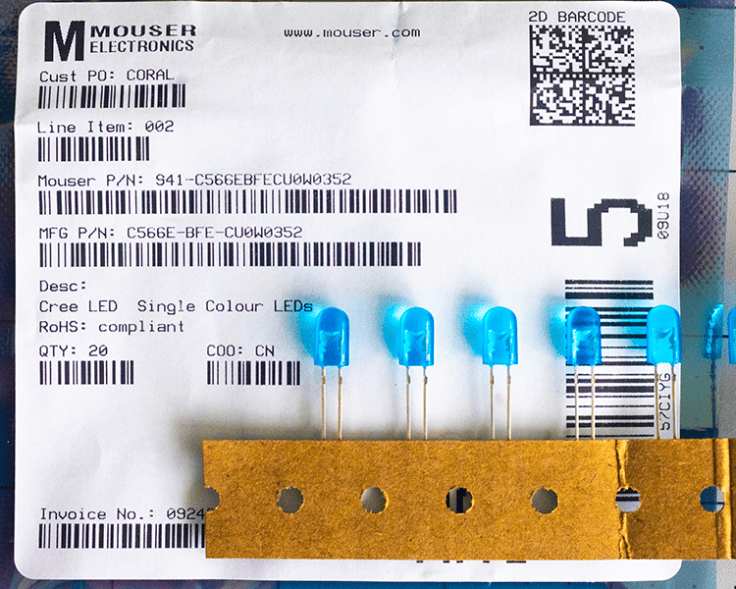
A label from Mouser Electronics showcasing a product order, featuring details like item number, description of Cree single color LEDs, and a quantity of 20, alongside several blue LEDs attached to a brown card.
LED bulbs royal blue ~460nm.
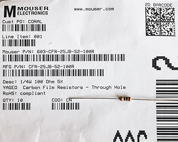
Receipt for a purchase from Mouser Electronics, featuring carbon film resistors, including details such as part numbers and quantity.
One of two options for resistor choices needed to protect the LED.
A blue LED and a resistor connected by wires on a grid background.
Solder the resistor to the positive end of the LED and to the (+) side of the power supply.
A black flexible hose with a red lever and a clamp attachment, laid out on a grid background.
Stiff goose neck support modified by zip ties holding a series of plastic hose couplings. The cable was passed through the couplings
Close-up of a fiberoptic cable with a black rubber sheath, showing an end glow, and an LED with a resistor assembly double wrapped in heat shrink.
The LED is in direct contact with the fiberoptic cable
Close-up of a metallic component with grooves and a circular opening, set against a grid background.
Heat sink with central hole enlarged by drilling to fit the cables.
Close-up of a cable showing a heat sink and labeled connection points for optical and electrical connections.
Fiberoptic cable press fit end to end with the LED power cable held together by the heat sink.
Close-up of a black cable with electrical connectors, lying on a grid-patterned surface.
Completed optical and electronic transmission cable assembly.
Close-up of black tubing secured with zip ties to provide support for a fiberoptic cable.
The tubing allows the cable end to be advanced or retracted from the specimen.
A photo of a gooseneck light fixture, featuring a weighted stand, a power plug, and a light connection, with labels indicating each component.
Completed assembly of the Knapp fiberoptic illuminator. The weight stand is not specific but must be suitable to provide stability.
Close-up view of a microscope focusing on a glass slide illuminated by blue light.
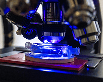
Custom, closed cell, micro aquarium illuminated by the ~460nm light directed on the surface by the glow end of the fiberoptic cable.

Discussion:

The bulb/resistor assembly could have been compartmentalized to allow quick interchanging with alternative resources however at this time this combined unit is sufficient for the requirements of this project. Resistor may be exchanged to provide different brightness. The LED may be exchanged for different wavelength. I have not tried alternative wavelengths. Ultraviolet wavelengths might be interesting. The one meter length of fiberoptic cable probably could be shortened by 1/2 to reduce light transmission loss. I expect that this device would provide excellent direct illumination for nearly any standard microscope.

Resistor and Power Calculations:

A 5mm oval 460nm (blue) Cree C566E LED typically operates at a forward voltage (V_{f}\) of approximately 3.2V. To run it safely at a standard target current of 20mA (0.02A) from the 6V supply, use the following specifications:

Calculated resistance: (140 Ohm) Uses a standard 150 Ohm resistor.

Resistor Power Dissipation: The resistor will drop 2.8V at 0.02A, dissipating 0.056W. A standard 0.25W (1/4 watt) resistor is sufficient. (Note: While the power supply can deliver up to 2A, the resistor ensures the LED only draws the 20mA it requires). If the 20mA is not bright enough for fast shutter speed photography through the SPLAN 40 (which has a narrower aperture and requires more light), the Cree C566E lamp can tolerate power up to 30mA. To attain the 30mA Formula: Swap the resistor for a (100 Ohm) component. This increases brightness by 50% but will make the LED run slightly warmer. The included LED enclosure design is a small aluminum heatsink.

DIY cost not including power supply ~$30.00

#microscope #illuminator #light source #direct lighting #blue light #fiberoptic #bioluminescence

If you wish to be notified of future postings please enter you email and click on subscribe

Please feel free to comment. Don’t forget to like this post!

Powered by WordPress.com.

Up ↑