Olympus BH2/BHS Illuminator DIY Upgrade

FABRICATION OF A REPLACEMENT SUBSTAGE LIGHT SOURCE FOR THE BH2/BHS MICROSCOPE

A square electronic component with a black cylindrical outlet and a ribbed ventilation grill on top.

Figure 1.  Olympus OEM illuminator housing, bulb, magnifier, diffuser, mounting tube and electrical connector. Not included in image are the transformer, electrical components and controller which are in the base of the microscope

The purpose of this posting is to satisfy the needs of amateur microscopists using Olympus model BH2/BHS with a failing illuminator. It is designed to be low cost, easy to fabricate, install.and maintain.

The BH2/BHS microscope has a substage incandescent light source that is standard with the instrument. The light source required a 120 V power source which is modified by a transformer and microcircuitry built into the base. There are two controllers for this lamp including a on/off power switch and a sliding potentiometer for intensity control. 

PROBLEM STATEMENT:

The sliding potentiometer is no longer in production  and all online inventory resources for a single replacement this part are out of stock. My Olympus BH2/BHS potentiometer was out of function. Attempts to clean it without disassembly of this substructure were unsuccessful. The other option was to replace the entire light source system with a new low voltage LED bulb.

The housing for the new light source was fabricated from easily available PVC plastic plumbing materials. Other materials listed below were easily purchased from online suppliers. 

LIST OF PARTS OF THE ASSEMBLY:

1 !/2 X 2-inch PVC coupling

2″ PVC Pipe Vent Screen, 2.375″ OD, 1/2″ mesh

5/8-inch length of 1-inch PVC plastic pipe

Low voltage DC power cable, 5.5mm X 2.1 male connector ~ 10 inches of  ~20 ga twin wire

Round Heat sink,  1 inch outside diameter, 2-inch length with internal space for placing screws

2 machine screws to fit the apertures in the heat sink (your choice)

2-inch disc of sheet ~1mm aluminum, (Secured from scrap packaging)

Aluminum tube 47mm OD X 78mm length 

LED star with light frequency of your choice. (I used 460mm for the royal blue).

Thermo-adhesive for attaching LED star to the heatsink 

Metallic duct tape to apply to the ID of the microscope substage rear illuminator port

Plastic 0.5mm clear plastic shim stock, (1cm X 15cm strips cut from scrap packaging)

TOOLS NEEDED:

Saw, to cut PVC and aluminum tubing (hand saw or power miter saw)

Scissors, to cut sheet aluminum and plastic

Soldering tool, for micro circuitry with rosin core solder

Thread tap, with sized drill bit for attaching the heat sink to the sheet aluminum mounting plate

Power drill motor

POWER SOURCE:

Variable Power supply available and purchased from the Empire of Dirt Workshop (empireofdirtworkshop.com) or contact Carl (carlh6902@gmail.com)

Disclaimer: I did not collaborate with Carl regarding the use of his power source. He makes his own design exclusively for Olympus BH2 microscopes. This illuminator is my design for BH2/BHS Olympus microscopes.

RESULT:

The new Olympus BH2/BHS microscope illuminator together with the power source provides perfect lighting for Olympus SPlan 5X, 20X, and 40X lenses. The heat generated from the illuminator assembly is minimal. Heat generated from the power source is also well dispersed from the heat sink of the power source. 

I constructed three light sources using this method; white light, royal blue and royal blue with a fiberoptic cable for direct illumination. The royal blue light provides illumination to reacts with the green fluorescent protein in the marine organism subjects. 

The internal electronics in the base of the microscope are not used but remain to maintain the mass of the instrument thus reducing photographic image blur from extraneous vibrations.

COST:

Not including the transformer and power source, the total cost of parts and materials was less than $50. Including the initial cost of the first unit the cost of three illuminators was less than $75 and I still have excess remaining materials.  

Note Not shown here is the fiberoptic illuminator. That deserves its’ own presentation.

ILLUSTRATIONS:

A close-up view of a white plastic pipe fitting on a grid pattern background.
Figure 2  PVC coupling
A white circular plastic ring placed on a grid-patterned surface.
Figure 3  section of PVC 1-inch pipe
White PVC pipe fitting viewed from above, showing a circular design with an inner diameter.
Figure 4  Check of fit of PVC pipe inside of coupling
Three white plastic pipe fittings on a gray grid background, including a round connector, a smaller ring, and a circular grating cover.
Figure 5 PVC parts to make illuminator housing
A broken white ring placed on a grid-patterned surface.
Figure 6  Section of PVC with V shaped split to trap wire
Close-up of a white circular plastic pipe fitting on a grid mat.
Figure 7  PVC coupling with notch to accommodate wire
A white PVC pipe fitting, a round metallic disc, and an aluminum heatsink on a grid-patterned surface.
Figure 8  PVC Coupling with sheet aluminum and heat sink
Top view of a white plastic container with a metal base featuring two holes.
Figure 8  Sheet aluminum with holes drilled to receive retaining screws
An electrical wire with a 5.5mm x 2.1mm male connector, an LED circuit board, and a heat sink on a grid surface.
Figure 10  Electrical components ready to assemble.

Close-up view of a LuxorDrive component with textual details and electrical contacts on the top surface.
Figure 11 LED star glued to heat sink.
A white PVC pipe fitting next to a circular aluminum LED heat sink with electrical wiring attached.
Figure 12  Heat sink with wired soldered to LED star, adhered to the heat sink and screwed to the plate ready for assembly into PVC housing.
Top view of a white LED light housing with wires and a circuit board inside.
Figure 13  Heat sink with wire and LED and mounting plate inserted into housing. Some notching was needed to pass the wire through the plate and the side of the interior of the housing
Close-up view of a white cylindrical device with electrical wires, placed on a grid-patterned surface.
Figure 14 Side view of heat sink with wire and LED and mounting plate inserted into housing.
Close-up view of a white plastic electrical junction box with two screws inside and a black wire attached, next to a removable cover with a grid pattern.
Figure 15  View of the interior of the larger end of the PVC housing. Note the path of the wire through the notched plate and housing side and retained in the V of the split ring of PVC. Notch in end cap.
A cylindrical metal tube with a smooth surface, placed on a grid-patterned surface.
Figure 16  The aluminum tube to be used for mounting to the microscope
Disassembled components of a lighting fixture including a white socket, a gray cylindrical body, a mounting ring, and a white grid cover.
Figure 17  Full display of parts in the illuminator ready for final assembly.
A disassembled device featuring a cylindrical metal base with a white plastic top, a black wire protruding from it, and two separate white plastic components including a ring and a cover with a grid pattern.
Figure 18  Rear stack of PVC parts 
A white and silver cylindrical container with a removable top and a grid-patterned cover next to it. A black wire is visible inside the container.
 Figure 19  Wire captured in split ring ready to close with the vented cover.
A close-up of a cylindrical device with a white top featuring a grid pattern, attached to a metallic cylinder below, and a black wire extending from the side.
Figure 20  Fully assembled illuminator. Use sheet plastic shim stock to fill the spaces and make a sturdy assembly.
Close-up of a cylindrical opening on a machine with a textured surface and control dials.
Figure 21  Interior of the rear illuminator light port modified with parches of 4 layers of aluminum duct tape to make a snug fit for the new illuminator
Close-up of a ventilation grille on the back of a device, featuring a circular design with a grid pattern and a cable attached.
Figure 22  LED illuminator in place ready for first light.
A collection of four electrical components arranged in a row on a grid background, labeled as Transformer, Power Supply, White Light, and Royal Blue Light.
Figure 23  Completed illuminator replacement kit including transformer, variable power supply, and both the white light source and blue light source.
Image showing a power supply unit on the left, and two light fixtures labeled 'ROYAL BLUE' and 'WHITE' on the right, casting different colored lights.
Figure 24 Power source illuminating both white and blue LEDs
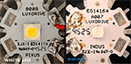
Top view comparison of two LED light components, one labeled 'White LED' and the other 'Blue LED,' showcasing their different color chips and design features.
LED lights: White LED Star Cree XLamp B009-CL2075OU3; Blue LED Star Cree XLamp XT-E Royal-Blue A007 E514064

I made two illuminators for specific purposes. The white is for general transillumination. The royal blue is for study of coral polyps with green fluorescent protein bioluminescence. I hope that this keeps all of the Olympus BH2/BHS microscopes working for more years to come.

Just wait until you see the fiberoptic direct illuminator.

If you wish to receive notification of postings please enter your email and click on subscribe.

Please enter your comments in the space provided.

Bauhinia and Hibiscus: A Comparison of Floral Reproduction

This posting is a response to the numerous hits made on a previous posting featuring the Non invasive Bauhinia tree. It seems that the interest lies in its reproductive nature. The purpose of this post is to improve the understanding of plant biology through comparative anatomy.

The title image shows the Bauhinia (blakeana ) on the left and the Florida native scarlet rosemallow (Hibiscus coccineus) on the right. I photographed the Bauhinia in the roadway median of our neighborhood. I photographed and display the scarlet rosemallow because it is such a stunning finding in the fresh water marshes of the Corkscrew Nature Preserve in SW Florida. It also shows that it is not a cultivar but it can self propagate without human intervention. Both plants are eye candy that must be appreciated in their out-of-door surroundings. In our community we have domesticated tropical hibiscus which are close relatives to the wild scarlet hibiscus

These two blossoming plants attract loads of attention. The Hong Kong orchid (Bauhinia blakeana ) and the cultivated tropical Hibiscus (Malvaceae) produce wonderful, flamboyant, visually attractive flowers. They are planted throughout our community. Additionally, these blooms have great staying power lasting for many months. Their flowering period stretches anywhere from eight to ten months, from September to June. They have, however, remarkably different reproductive powers. To reveal the secret of these two plants this posting compares the gross and micro anatomy of their two flowers.

A detailed diagram of a Bauhinia flower labeled with its anatomical parts, including bud, petal, sepal, stamen, pistil, ovary, style, and stigma, showcasing the flower's structure.
Bauhinia blossom with some pettals removed
Diagram labeling parts of a hibiscus flower including the stamen, ovary, style, stigma, petal, and sepal, accompanied by lush green leaves and a bud.
Hibiscus blossom with no petals removed

Gross and micro dissection reveals the major difference in the reproductive capacity of the these two perfect flowers. Dissection and microscopic examination of the ovaries shows that the hibiscus has ovaries while the bauhinia has no trace of ovules. It is unable to sexually reproduce.

Diagram illustrating the anatomy of a Bauhinia flower, highlighting its various parts including petal, sepal, stamen, anther, filament, ovary, style, stigma, and pistil. The text indicates that the flower is perfect but sterile, with no ovules or seeds.
This is a full dissection of the Bauhinia × blakeana blossom. Look at the top left images. You can see that under microscopic examination there are no ovaries within the ovary. This plant is infertile.

Anatomy diagram of a hibiscus flower, illustrating the components like the ovary, stigma, stamen, and petals, labeled with descriptions to explain its reproductive functions.
This is a full dissection of the Hibiscus blossom. Look at the top left images. You can see that under microscopic examination there are ovules within the ovary. This plant can produce seeds. It is fertile.

The five-petaled blossoms of Bauhinia plants are known as “perfect flowers,” because each individual bloom contains both female and male parts. Some varieties of the Bauhinia flower, such as the widely cultivated Hong Kong Orchid Tree (Bauhinia × blakeana), are known to be sterile. Bauhinia are monoecious, which means “single house”. This designation describes the dual sexual capacity in a single flower. The flowers can self pollinate or fertilize with pollen from another plant. The flowers attract pollinators such as hummingbirds, bees, butterflies, and more. Bauhinia × blakeana‘s sterility is due to its hybridization. Bauhinia blakeana is the result of conjugation of the very similar species Bauhinia purpurea ( Purple Camel’s Foot) and Bauhinia variegata ( Camel’s Foot Tree). Both of these are exotic species according to the Hong Kong Herbarium. The parent plants have partially overlapping flowering periods and geographical habitats, and the same range of bee and butterfly species as pollinators. Interbreeding Bauhinia purpurea and Bauhinia variegata is probable. The resulting triploidy of this plant has probably rendered this varietal sterile. The plants you see today are clones of the same flowers seen by Hongkongers more than a century ago. They are propagated asexually through cultivation of stem cuttings.

The Hibiscus is also considered a perfect flower which actually produces viable seeds. The hibiscus is a genus of flowering plants known for their large, showy flowers, belonging to the mallow family (Malvaceae). Fertilization of these plants is complex. Pollination may fail because of these five prerogatives.

  • Self-Pollination: Some hibiscus varieties are self-pollinating. This can make it difficult to cross-pollinate them.
  • Timing: Hibiscus flowers are only receptive to pollen for a short period, usually just a few hours.
  • Pollen Viability: Hibiscus pollen can lose its viability quickly.
  • Stigma Receptivity: The stigma needs to be receptive to pollen. The stigma, gateway to the ovarian, might not be receptive at the same time the pollen is viable.
  • Germination: Seeds take 12 to 24 months to bloom.

The hundreds of species of hibiscus are generated through human intervention of the pollination. Tropical hibiscus are propagated sexually from seeds or asexually from stem cuttings or plant division. In carefully controlled environments and with delicate, patient effort botinists have hybridized the tropical hibiscus to make hundreds of beautiful new varieties. The new plant varieties are propagated from cuttings or division to produced plants which are clones of their parents.

Illustration explaining hormonal fertility signals in plants during pollination, detailing four key hormones involved in the process.
In addition to timing, these four hormonal obstacles must be passed in the carpel for signaling a specific selection of pollen appropriate for germination of ovules in these species.

DISCUSSION of FINDINGS:

This is not a thorough scientific data collection. Three samples of blossoms from each of two trees were collected for a total sample size of six. All of the samples were made on the same day in April, 2020. There were no major local meteorological events for the year preceding this observation. There were no observations of the viability of the observed polled during this observation. Further study should be done to give this a high level of confidence of the conclusions.

SUMMARY:

In Florida the Bauhinia × blakeana and Hibiscus plants thrive and are found in almost all of the cultivated communities and household gardens. They are well tolerated but stable non-native species. Because of their reproductive limitations they are not invasive. We can feast our eyes on this banquet of form and color without fear of damaging the environment.

REFERENCE LINKS:

FEEDBACK:

Please use the box below for your comments.

If you wish to start a dialogue on this subject please use the Discussion Board.

For notification of new postings please enter your email address and click on the Subscribe box below

#Bauhinia #Hibiscus #reproduction #flowers #invasives #anatomy #seeds #sterile #

Geography – Okavango Delta and Maasai Mara Savanna

UNDERSTANDING THE TWO ECOLOGICAL SYSTEMS BY COMPARING THEM FROM THE GROUND UP.

To help understand what is happening in this system it may be made easier by look at its parts. There may be some errors in this method but at least this is a reasonable hypothetical start. Let’s begin with the idea that every detail is important and that everything is interconnected. Also, if a part of the system is lost the entire system is compromised. See the map at the end of this posting.

The featured image shows one of thousands of termite colony mounds

The Okavango and Mara locations are very different not only in location and elevation but also in geology. Two soil samples were taken from typical road side areas in the savannah-like landscapes away from human traffic areas. Under the microscope you can see that the individual sand grains are transparent, something which is not obvious when looking at the sand with the unaided eye. The sand of the Delta (Fig. A1 & 2 is made up mostly of silicon dioxide (SiO2). It is completely glassy. It is not soluble and has no mineral content. Volcanic pumice Fig B1 & 2 is a complex particle aggregate of ash feldspar. It is an incomplete glass with other minerals at the particles’ surfaces. The Mara soil has a much higher metabolizable mineral content which makes the soil more fertile than the Delta.

Fig A1. Sand particle sample from Okavango Delta. (20X) Completely translucent. Illuminated with transmitted plane light. This is nearly pure silica.
Fig. A2. Sand particle sample from Okavango Delta. (20X)
Completely translucent. Illuminated with transmitted polarized light.
Fig.B1
Sand particle sample from Mara.
Note the surface’s complex micro-porosity. Illuminated in dark field with direct lighting. This amorphous, opaque particle is definitely volcanic in origin. (20X)
Fig. B2.
Sand particle sample from Mara. (20X) Completely opaque. The red color is iron oxide. Illuminated in dark field with direct lighting.

–—+—-

OKOVANGO DELTA

The Delta is flat but it is cyclically flooded and the colors are green and tan. The islands of the Delta were built by the humblest of creatures. The termites as architects, engineers and builders have created a landscape of unbelievable variety. They harvest the dead plants and with the sand of the Kalahari desert and they build massive, nearly indestructible castles reaching meters into the sky. The nest height is determined by the water level. The higher the water level, the taller the nest will be. When the population reaches a critical mass, a new colony is initiated. With erosion by water, wind, and the burrowing of animals the mounds collapse and islands grow. As a result of centuries of this cycle the islands provide a collective of soil used by the large mammals, birds and fish. The aquatic plants are supplemented by grasses, brush, bushes, and trees. These form savannas in the Delta for non-migrating herds of grazing land animals and the creatures which accompany them. They also encourage aquatic animals like fish, birds, reptiles, and mammals which are supported by the aquatic environment. 

Termite mound on savannah island of the Okavango Delta
Pampa Grass (Niscanthus junceus) Assists in forming islands by trapping sand and with decaying plants supports rooted water plants such as water lillies.
Blue Water Lilly (Nymphea nouchali). These also assist in the formation of islands and support protective areas for aquatic animals.
Marshland in the Okavango Delta with grazing zebras. The trees in the background are on the island that emerged from the work of the termites and plants.
Impala roaming through of the woodlands of the Okavango Delta. This land is based on the foundation of sand deposited by wind and water sediment which is fixed and enriched by termites and plants.
These zebras are grazing on a very large island in the Okavango Delta. It appears like a classic savannah landscape.
Tree covered island succumbing to salt accumulation in the Okavango. The islands dehydrate and accumulate salt at the periphery. When high water returns and infiltrates the interior of the island the salt enters the soil. Plants, weakened by drought, are further dehydrated and die.

The water levels rise and fall because of the flow of several rivers that end in the Delta. The water never reaches the sea; hence the Delta. Water is lost by evaporation and transpiration. The animals have a reliable supply of water and plants. They do not migrate.

—-+—-

MAASAI MARA

The Kenyan savannah is so starkly different from the Okavango Delta they seem worlds apart. The Serengeti plane colors are tan and beige. The Mara land is flat and dry. In contrast to the Delta, the Maasai Mara is the result of volcanism and rain.  Dominating the landscape is the ancient volcano of Mt. Kenya along with the range of uplands that are a result of the enormous energy expended in tectonic plate collision and the spread of the great Rift Valley. It stands as a plateau at an elevation of about 1,480 to 2,280 meters. The volcanoes of the area have created a mineral rich soil which when watered by the seasonal rain provides an opportunity for lush grass to grow. There are few trees growing on the savanna of the Mara making it seem like a great lake of soil dressed in golden grass. The Mara also has riverine forests. The seasonal rains are predictably distributed regionally causing the rotation of the animal migration. The people of the Maasai tribe move their domesticated herds in synchrony with the wildlife, plants and rainfall. 

When looking at the landscape of the Maasai Mara it is nearly unavoidable to escape the surrounding mountains replete with volcanoes. Mount Kenya (ancient volcano) is just to the right side of the image. The ash of these are the source of the soil. The sand particles seen in Figs. B1&2 came from these volcanoes. Note how dry it is in this region.
Mara river cutting through the savannah. The river is a limited but reliable source of water. Seasonal rain is the major water resource however it is variable and recently very deminished.
Hillsides erosion adds to the plane.
The massive savannah of the Serengeti plane supports an animal migration that may be the greatest seasonal movement of animals on earth. The grass is lush and green.
Mount Kenya off in the distance as part of the Great Rift Valley. No migratory animals here.
This map* of the central eastern sextant of the continent of Africa shows the relative position of the two areas of our grand safari.

These two systems are much more complex than this simple description. This only becomes apparent after returning from there, collecting and organizing observations, and reflecting on the diversity and life forms and cycles. This leads to many more questions such as: Where did the glassy sand come from? Why do the two areas share so many identical species? Why are there so few cactus or pine species? How would you summarize the comparison of these two areas? Perhaps these questions can stimulate discussion in our comment section.

* Modified from African Safari Planning Map, 3rd ed. African Adventure Company 2018

#Kenya #Botswana #termite #savannah #sand #Kalahari #desert #map #Africa #great rift valley #Serengeti #Mara #Okavango #woods #marsh #zebra #impalla #great migration

If you wish to receive notification for new postings please enter your email and click on subscribe. If you also wish to participate in discussion or make comments please leave a reply.

To Tree or Not to Tree

Is a palm tree not a tree? In categorizing plants and animals for the Everglades Ark Epicollect5 data base I was conflicted in assigning the characteristics of trees to palms. I have called them palm trees forever but they really look different from oak, olive or other trees. Checking out the definition of a tree resulted in an ambiguous answer.

Featured image: In a spin about palms

Definition of tree: From a technical standpoint, palms fit American Forests’ current definition of trees, as they are woody plants with an erect perennial stem or trunk, at least 9.5 inches in circumference at 4.5 feet above the ground. They also have a definitively formed crown of foliage and a height of at least 13 feet. 

This still didn’t satisfy my curiosity. I still wondered why they were so different. Here are photographs of tree aspects to show the physical differences:

Tree landscape view

Olive tree, rigid and arborized branches
standing adjacent to palm
Palm tipped by heavy wind storm

Leaf patterns

Central vein with alternating branched secondary veins
Radial symmetry of straight palm leaves with straight unbranching veins

Photomacrograph leaves

Here is a demonstration of reticular veining ~35X
All straight, parallel veining without branching ~35X

Photomicrograph of leaves

Branching veins becoming progressively smaller as they branch ~600X
Straight, parallel veins even at the microscopic level at ~800X

Common biology of both di and mono cotyledonous plants. Both have chloroplasts for metabolism and stoma

Stoma are more randomly disbursed in the leaf surface. The stoma are on the underside of the leaf in the dicot group ~800X
Xylem and phloem circulation and stoma for respiration. The stoma are on the upper side of the leaf ~800X

Tree roots

Broad and deep root system of dicotyledon, olive tree adjacent to monocotyledon palm.
Root ball of monocotyledon, palm exposed by erosion

Tree cross sections

Tree rings show annual growth and suggest weather conditions. Specialized bark system.
No rings and no mechanism to repair. Bark is a remnant of leaf system.

Tree behavior to injury

Progressive but not yet complete healing of dicot tree

There is no mechanism for healing in palm trees.

Flowers

All dicots have five petals to their flowers

No petals but other monocots have three petals

Here is a list tabulating differences in the characteristics between the tree types.

Aspects:Palm True tree
Rootsshallow multiple small distributeddeep, branching with tap root
Trunkthe trunk is actually the stem which bendsthick, rigid
Branchesno branchesmultiple arborizations
Leavesveins begin at the base, run parallel to the length of the leaf, stoma on upper leaf surface central veins with multiple arborizations to leaf periphery, stoma on lower side of leaf
Outer surfacestumps of old growth leaves, no structured interior wood specialized bark covering wood
Trunk corefibrous without annular ringswoody, highly structured interior nutrient flow system
Interior structurefibrous with layered leavesorganized circulatory system, annular growth rings
Recoverycannot repair injury or diseasecan heal wound and fight disease
Developmentmonocotyledondicotyledon
DNAGrassTree
Comparison of plant distinguishing characteristics

A palm tree is really a palm grass.1 They are monocotyledons. Genetically they are similar to other grasses like bamboo. They are resistant to storm damage fracture because of their lack of a woody interior structure but are more subject to uprooting because of their shallow roots.

Grasses are flowering plants that are members of the monocot class that also include corn, rice, lilies, orchids and palms. Now that I understand what a palm is I can more freely post palm types, flowers and fruits. Later I will show the microscopic view of tree anatomy pointing out differences between monocots and dicots.

This subject opens a wide spectrum of ideas regarding plants. We have already broached the idea of cotyledons. There is much more to explore including the microscopic examination of cross sections of plants and their appendages or stems, roots and flowers as well as angiosperms vs gymnosperms and the role of sexual vs asexual reproduction and seed development.

The micrographs shown here are all done with simple direct bright field and transmitted light. Just wait until we get into cross sectional, stained, transmitted plane, and polarized light illumination!

The Epicollect5 database will be modified to reflect this altered view of classification.

  1. References:

Dicot vs monocot

Palm leaf anatomy

Plant vascular system

Plant leaf anatomy

#tree #palm #monocot #dicot #monocotyledon #dicotyledon #veins #stoma #annular rings #reticular veining #petals

If you like it click like. Enjoy it then share it. If you have experience say it in comments.

For notification of new postings enter your email and click subscribe.

Microscopy, A New Tool in Our Armament

In the blog about Photomicrography you could easily see the detail of the butterfly wing scales. This valuable insight is not only beautifully patterned and dramatically colorful it also shows the remarkable complexity of the wing. This was done with a very low cost microscope and a cell phone. We also spoke earlier about the simple Gear used in this voyage of discovery. To expand the range of observations and bring more sense into the discussions I acquired a more sophisticated microscope.

New microscope

The addition to the observation gear is an Olympus BH 2 BHS trinocular microscope with five Splan objective lenses including oil immersion, light source adaptable to ultra blue illumination, photo extension with NKF 2.5X L microscope eye piece, and a Olympus OM to Canon EOS 5D mark II camera adaptor. The system was created by referencing the Alan Wood web site.1

Freely available microscope description downloaded from internet.1

New microscopic methods

The new scope has bright field, dark field, polarized light, color filtered light and flash direct lighting. These provide the opportunity to make observations of samples that may be unstained, vital and devital stained and fluorescent illumination.

Computer Assisted Photomicrography

In 2021 Canon made available a free downloadable software interphase to couple the camera to the Apple macOS Monterey on the Mac Pro computer. This allows a seamless control of the attached camera and a recording of still and video microscopic observations. Using this software, the camera can be remotely controlled without shutter or mirror camera vibration. The resulting photo micrographs can be loaded directly to the local hard drive or to the cloud with this arrangement.

Fully operational observation system assembling the microscope, digital camera and MacPro computer at the work station. The image on the monitor is the first light, live view of a cross-section of mammalian bone using polarized light.

Accessories

There are also a number of accessories including hand microtome, ring light flash light and full slide mounting, staining accessories and supplies for mounting and cleaning.

Sharing the Opportunities

Additionally, I donated my American Optical trinocular bright field microscope to the Wonder Garden of Bonita Springs FL to assist in observation of micro anatomy and pathology of their animals and plants and for live demonstration for their education programs. This was done in the spirit of exploration and expansion of horizons for others. We are all together on this discovery voyage of the Everglades Ark.

For further discussion for the amateur microscopist check out the website Microscope Clarity.2 Included in that site are discussions, recommendations for gear and supplies and experiments for novice microscopists.

References:

  1. Alan Wood Olympus microscopes
  2. Microscope Clarity

If you are a microscopist or are interested in the subject please make your comments in the space below!

To receive notifications of latest posts enter your email and click on subscribe.

#microscope #polarized light #ultra blue light #bright field #dark field #oil immersion #slides

Powered by WordPress.com.

Up ↑